

Probando el Conversor Analógico Digital
1. Introducción:
Continuando con las prácticas, ahora le toda el turno al conversor Analógico-Digital. Este es un periférico que seguramente
usaremos más adelante.
2. Características del conversor A/D:
El conversor analógico-digital, mide el voltaje en un pin y nos proporciona un valor relativo a una referencia.
Como referencia normalmente, se utiliza la tensión de alimentación (Vcc ó Gnd) pero podemos usar otra tensión a través de los pines Vref+
(RA3) y Vref- (RA2). Con esto conseguimos tener más resolución ya que podemos ajustar la amplitud.
Si queremos medir una señal que varía entre 0Vcc y 5Vcc usando 10 bits, tendremos saltos de 4,9mV.
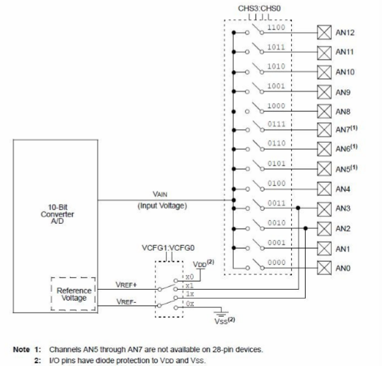
El PIC18F4550 tiene 13 entradas analógicas, pero asociadas a un único conversor. Esto quiere decir que podemos hacer
lecturas desde todas las entradas, pero no simultáneas.
El tiempo necesario para completar una conversión está en torno a 1-2uS.

Nota: Hay que tener en cuenta que este uControlador soporta como máximo 5Vcc
en sus pines. No podemos medir tensiones superiores directamente.
3. Registros del Conversor A/D:
En los pic, la configuración y consulta de estado de los periféricos integrados se hace mediante registros:
3.1. Registro ADCON0:
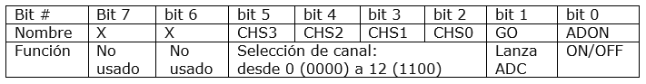
Este registro tiene las siguientes funciones:
- ADON: Activa (1) o desactiva (0) el conversor.
- GO/DONE: Empezamos la conversión (1). Cuando pasa a 0, la conversión se ha realizado.
- CHS3, CHS2, CHS1, CHS0: Selecciona el pin a usar para la conversión.
3.2. Registro ADCON1:
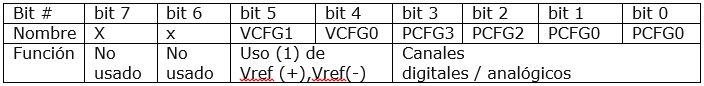
- VCFG1 y VCFG0: Nos permite seleccionar la referencia de tensión. VCFG1 = 0 -> GND; VCFG1 = 1 -> pin Vref-. VCFG0 = 0
-> Vcc; VCFG0 = 1 -> Vref+.
- PCFG3, PCFG2, PCFG1, PCFG0: Configura el canal como entrada analógica. Todas las entradas como analógicas = 0x0F.
3.3. Registro ADCON2:
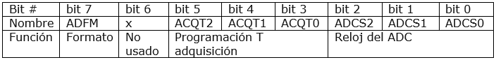
- ADFM: El resultado de la conversión se guarda en dos registros de 8 bits cada uno (ADRESH, ADRESL).
- ADFM=0: Se suele usar si sólo queremos los 8 bits más significativos. En ese caso basta con hacer: res=ADRESH.
- ADFM=1: Se suele usar cuando nos interesan los 10 bits de la conversión. El resultado se puede pasar a un entero de 16 bits: res=(ADRESH<<8)+ADRESL
- ACQT2, ACQT1, ACQT0: Permite configurar un tiempo de espera desde que indicamos el inicio de la conversión. Así no tenemos que estar perdiente de si ha pasado el tiempo para poder leer. Si todo 0, debemos estar pendiente del tiempo de conversión mínimo.
- ADCS2, ADCS1, ADCS0: Permite escoger la frecuencia para la conversión. Según el pic usado, podremos usar una frecuencia máxima: F ad = Fosc / div.
4. Modificando las librerías existentes:
Nos vamos al directorio de instalación de las MLA y modificamos los ficheros "adc.c" y "adc.h"
4.1. Adaptando "acd.h":
/******************************************************************** Software License Agreement: The software supplied herewith by Microchip Technology Incorporated (the "Company") for its PIC(R) Microcontroller is intended and supplied to you, the Company's customer, for use solely and exclusively on Microchip PIC Microcontroller products. The software is owned by the Company and/or its supplier, and is protected under applicable copyright laws. All rights are reserved. Any use in violation of the foregoing restrictions may subject the user to criminal sanctions under applicable laws, as well as to civil liability for the breach of the terms and conditions of this license. THIS SOFTWARE IS PROVIDED IN AN "AS IS" CONDITION. NO WARRANTIES, WHETHER EXPRESS, IMPLIED OR STATUTORY, INCLUDING, BUT NOT LIMITED TO, IMPLIED WARRANTIES OF MERCHANTABILITY AND FITNESS FOR A PARTICULAR PURPOSE APPLY TO THIS SOFTWARE. THE COMPANY SHALL NOT, IN ANY CIRCUMSTANCES, BE LIABLE FOR SPECIAL, INCIDENTAL OR CONSEQUENTIAL DAMAGES, FOR ANY REASON WHATSOEVER. *******************************************************************/ #ifndef ADC_H #define ADC_H #include#include /*** ADC Channel Definitions *****************************************/ #define ADC_CHANNEL_POTENTIOMETER ADC_CHANNEL_0 typedef enum { ADC_CHANNEL_0 = 0, ADC_CHANNEL_1 = 1, ADC_CHANNEL_2 = 2, ADC_CHANNEL_3 = 3, } ADC_CHANNEL; typedef enum { ADC_CONFIGURATION_DEFAULT } ADC_CONFIGURATION; /********************************************************************* * Function: ADC_ReadPercentage(ADC_CHANNEL channel); * * Overview: Reads the requested ADC channel and returns the percentage * of that conversions result (0-100%). * * PreCondition: channel is enabled via ADC_Enable() * * Input: ADC_CHANNEL channel - enumeration of the ADC channels * available in this demo. They should be meaningful names and * not the names of the ADC pins on the device (as the demo code * may be ported to other boards). * i.e. ADC_ReadPercentage(ADC_CHANNEL_POTENTIOMETER); * * Output: uint8_t indicating the percentage of the result 0-100% or * 0xFF for an error * ********************************************************************/ uint8_t ADC_ReadPercentage(ADC_CHANNEL channel); /********************************************************************* * Function: ADC_Read10bit(ADC_CHANNEL channel); * * Overview: Reads the requested ADC channel and returns the 10-bit * representation of this data. * * PreCondition: channel is enabled via ADC_Enable() * * Input: ADC_CHANNEL channel - enumeration of the ADC channels * available in this demo. They should be meaningful names and * not the names of the ADC pins on the device (as the demo code * may be ported to other boards). * i.e. - ADCReadPercentage(ADC_CHANNEL_POTENTIOMETER); * * Output: uint16_t the right adjusted 10-bit representation of the ADC * channel conversion or 0xFFFF for an error. * ********************************************************************/ uint16_t ADC_Read10bit(ADC_CHANNEL channel); /********************************************************************* * Function: bool ADC_Enable(ADC_CHANNEL channel, ADC_CONFIGURATION configuration); * * Overview: Enables specified channel * * PreCondition: none * * Input: ADC_CHANNEL channel - the channel to enable * * Output: bool - true if successfully configured. false otherwise. * ********************************************************************/ bool ADC_Enable(ADC_CHANNEL channel); /********************************************************************* * Function: bool ADC_SetConfiguration(ADC_CONFIGURATION configuration) * * Overview: Configures the ADC module to specified setting * * PreCondition: none * * Input: ADC_CONFIGURATION configuration - the mode in which to run the ADC * * Output: bool - true if successfully configured. false otherwise. * ********************************************************************/ bool ADC_SetConfiguration(ADC_CONFIGURATION configuration); #endif //ADC_H
4.2. Adaptando "acd.c":
/*******************************************************************************
  Analog to Digital converter API (blocking, single channel) for PICDEM FS USB
  demo board.

  Company:
    Microchip Technology Inc.

  File Name:
    adc.c

  Summary:
    Provides basic ADC interface for demo purposes.

  Description:
    Provides basic ADC interface for demo purposes.  This implementation is
    blocking.
*******************************************************************************/

// DOM-IGNORE-BEGIN
/*******************************************************************************
Copyright (c) 2013 released Microchip Technology Inc.  All rights reserved.

Microchip licenses to you the right to use, modify, copy and distribute
Software only when embedded on a Microchip microcontroller or digital signal
controller that is integrated into your product or third party product
(pursuant to the sublicense terms in the accompanying license agreement).

You should refer to the license agreement accompanying this Software for
additional information regarding your rights and obligations.

SOFTWARE AND DOCUMENTATION ARE PROVIDED "AS IS" WITHOUT WARRANTY OF ANY KIND,
EITHER EXPRESS OR IMPLIED, INCLUDING WITHOUT LIMITATION, ANY WARRANTY OF
MERCHANTABILITY, TITLE, NON-INFRINGEMENT AND FITNESS FOR A PARTICULAR PURPOSE.
IN NO EVENT SHALL MICROCHIP OR ITS LICENSORS BE LIABLE OR OBLIGATED UNDER
CONTRACT, NEGLIGENCE, STRICT LIABILITY, CONTRIBUTION, BREACH OF WARRANTY, OR
OTHER LEGAL EQUITABLE THEORY ANY DIRECT OR INDIRECT DAMAGES OR EXPENSES
INCLUDING BUT NOT LIMITED TO ANY INCIDENTAL, SPECIAL, INDIRECT, PUNITIVE OR
CONSEQUENTIAL DAMAGES, LOST PROFITS OR LOST DATA, COST OF PROCUREMENT OF
SUBSTITUTE GOODS, TECHNOLOGY, SERVICES, OR ANY CLAIMS BY THIRD PARTIES
(INCLUDING BUT NOT LIMITED TO ANY DEFENSE THEREOF), OR OTHER SIMILAR COSTS.
*******************************************************************************/
// DOM-IGNORE-END

#include "adc.h"
#include
#include
#include


#define PIN_ANALOG    1
#define PIN_DIGITAL   0

#define PIN_INPUT     1
#define PIN_OUTPUT    0

/*********************************************************************
* Function: ADC_ReadPercentage(ADC_CHANNEL channel);
*
* Overview: Reads the requested ADC channel and returns the percentage
*            of that conversions result (0-100%).
*
* PreCondition: channel is configured via the ADCConfigure() function
*
* Input: ADC_CHANNEL channel - enumeration of the ADC channels
*        available in this demo.  They should be meaningful names and
*        not the names of the ADC pins on the device (as the demo code
*        may be ported to other boards).
*         i.e. ADC_ReadPercentage(ADC_CHANNEL_POTENTIOMETER);
*
* Output: uint8_t indicating the percentage of the result 0-100% or
*         0xFF for an error
*
********************************************************************/
uint8_t ADC_ReadPercentage (ADC_CHANNEL channel)
{
    uint8_t percent;

    switch(channel)
    {
        case ADC_CHANNEL_0:
            break;
        case ADC_CHANNEL_1:
            break;
        case ADC_CHANNEL_2:
            break;
        case ADC_CHANNEL_3:
            break;
        default:
            return 0xFF;
    }

    //A very crude percentage calculation
    percent = (ADC_Read10bit(channel) / 10);

    if(percent > 100)
    {
        percent = 100;
    }
    return percent;
}

/*********************************************************************
* Function: ADC_Read10bit(ADC_CHANNEL channel);
*
* Overview: Reads the requested ADC channel and returns the 10-bit
*           representation of this data.
*
* PreCondition: channel is configured via the ADCConfigure() function
*
* Input: ADC_CHANNEL channel - enumeration of the ADC channels
*        available in this demo.  They should be meaningful names and
*        not the names of the ADC pins on the device (as the demo code
*        may be ported to other boards).
*         i.e. - ADCReadPercentage(ADC_CHANNEL_POTENTIOMETER);
*
* Output: uint16_t the right adjusted 10-bit representation of the ADC
*         channel conversion or 0xFFFF for an error.
*
********************************************************************/
uint16_t ADC_Read10bit(ADC_CHANNEL channel)
{
    uint16_t result;

    switch(channel)
    {
        case ADC_CHANNEL_0:
            break;
        case ADC_CHANNEL_1:
            break;
        case ADC_CHANNEL_2:
            break;
        case ADC_CHANNEL_3:
            break;
        default:
            return 0xFFFF;
    }

    ADCON0bits.CHS = channel;

    ADCON0bits.GO = 1;              // Start AD conversion
    while(ADCON0bits.NOT_DONE);     // Wait for conversion

    result = ADRESH;
    result <<=8;
    result |= ADRESL;

    return result;
}

/*********************************************************************
* Function: bool ADC_Enable(ADC_CHANNEL channel, ADC_CONFIGURATION configuration);
*
* Overview: Configures the ADC module to specified setting
*
* PreCondition: none
*
* Input: ADC_CHANNEL channel - the channel to enable
*        ADC_CONFIGURATION configuration - the mode in which to run the ADC
*
* Output: bool - true if successfully configured.  false otherwise.
*
********************************************************************/
bool ADC_Enable(ADC_CHANNEL channel)
{
    switch(channel)
    {
        case ADC_CHANNEL_0:
            TRISAbits.TRISA0 = PIN_INPUT;
            return true;
        case ADC_CHANNEL_1:
            TRISAbits.TRISA1 = PIN_INPUT;
            return true;
        case ADC_CHANNEL_2:
            TRISAbits.TRISA2 = PIN_INPUT;
            return true;
        case ADC_CHANNEL_3:
            TRISAbits.TRISA3 = PIN_INPUT;
            return true;

        default:
            return false;
    }
}

/*********************************************************************
* Function: bool ADC_SetConfiguration(ADC_CONFIGURATION configuration)
*
* Overview: Configures the ADC module to specified setting
*
* PreCondition: none
*
* Input: ADC_CONFIGURATION configuration - the mode in which to run the ADC
*
* Output: bool - true if successfully configured.  false otherwise.
*
********************************************************************/
bool ADC_SetConfiguration(ADC_CONFIGURATION configuration)
{
    if(configuration == ADC_CONFIGURATION_DEFAULT)
    {
        ADCON0=0x01;
        ADCON1bits.PCFG = 0b1110;
        ADCON2=0x3C;
        ADCON2bits.ADFM = 1;
        return true;
    }

    return false;
}


/*******************************************************************************
 End of File
*/
- La función "ADC SetConfiguration (ADC_CONFIGURATION configuration)" es la que configura la forma de funcionar del conversor A/D escribiendo en ADCON0 y ADCON1.
- La función "ADC Enable (ADC_CHANNEL channel)" es la que selecciona el pin a usar en la conversión.
- La función "ADC Read10bit (ADC_CHANNEL channel)" devuelve un valor de 10 bits leído del pin indicado. Por ejemplo, si leemos una señal que varía entre 0 y 5V, nos devuelve valores comprendidos entre 0 y 1023.
- La función "ADC ReadPercentage (ADC_CHANNEL channel)" devuelve el porcentaje del valor leído.
5. Ejemplo:
En este ejemplo, lo que hacemos es leer una entrada analógica y la función nos devuelve un porcentaje que representamos en
un "vumeter" creado por los led de la placa.
/* * File: main.c * Author: Eduardo * * Created on 5 de junio de 2017, 17:16 */ #include#include "config.h" #include "typedefs.h" #include "led.h" #include "adc.h" #define _XTAL_FREQ 48000000 // se define la frecuencia FOSC -- Hay que tener en cuenta los preescalers usados void delay_ms(uint16_t); uint8_t a = 0; uint8_t value = 0; uint8_t numLed = 0; void main(void) { for (a=0; a < 8; a++) { LED_Enable(LED_D1 + a); LED_Off(LED_D1 + a); } ADC_SetConfiguration(ADC_CONFIGURATION_DEFAULT); ADC_Enable(ADC_CHANNEL_1); while (true) { value = ADC_ReadPercentage(ADC_CHANNEL_1); if (value < 12 ) numLed = 1; else if (value > 12 && value < 24) numLed = 2; else if (value > 24 && value < 36) numLed = 3; else if (value > 36 && value < 48) numLed = 4; else if (value > 48 && value < 60) numLed = 5; else if (value > 60 && value < 72) numLed = 6; else if (value > 72 && value < 84) numLed = 7; else if (value > 84) numLed = 8; for (a=0; a < 8; a++) { LED_Off(LED_D1 + a); } for (a=0; a < numLed; a++) { LED_On(LED_D1 + a); } delay_ms(100); } } void delay_ms(uint16_t i) { for ( uint16_t x = 0; x < i; x++ ) { __delay_ms(1); } }
5.1. Práctica:
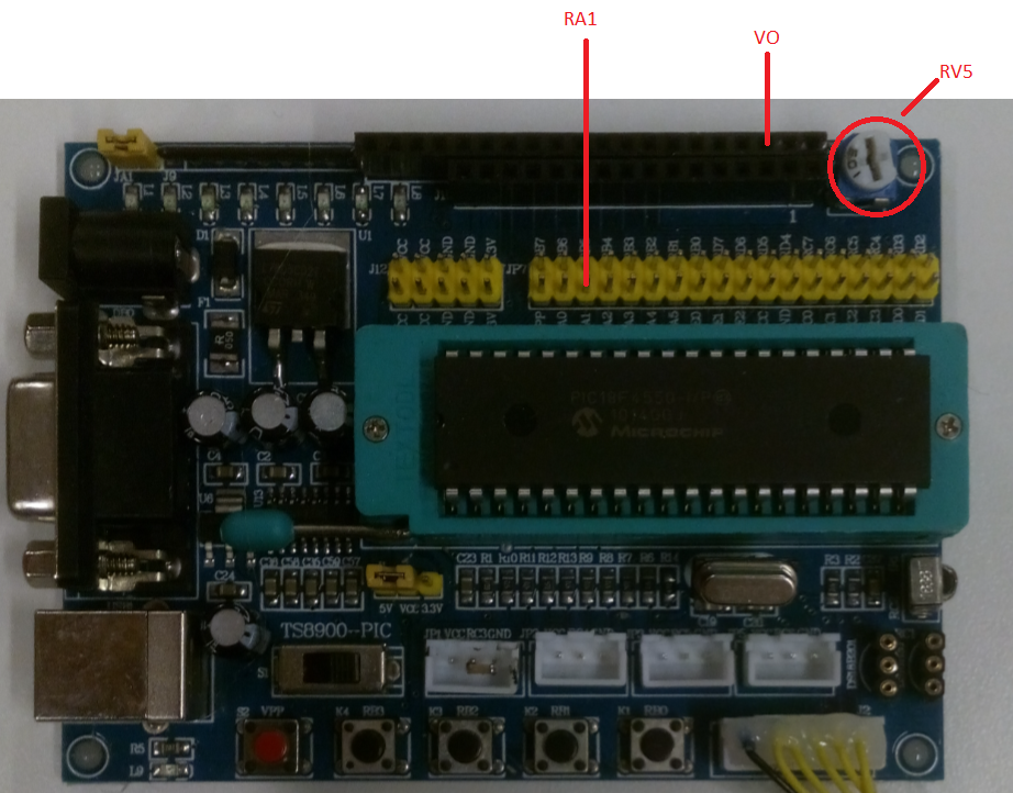
Para realizar la práctica, usaremos el potenciómetro que regula el contraste del display lcd (RV5), haciendo un puente entre el
pin "RA1" y el pin "V0":
- Vúmetro funcionando:
6. Descargas: